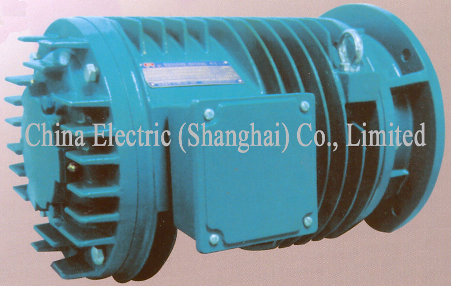
· Features and application YG series (H100-225) is a new-generation high reliability motor for roll table designed by our factory on the basis of JG2 and with reference to RM series of ABB Co. It has the features of small volume, lightweight, good performance, reliable operation, convenient maintenance, etc. Bearing grease replenishing device is equipped to allow use of high-temperature grease and to enhance the motor’s mechanical strength. Its comprehensive technical and economic indexes reach domestic advanced level and are comparable to that of RM series roll table motor of ABB Company.
YG series roll table motor can continue working when frequently starting and rotating clockwise and anticlockwise or under shocking load like reverse braking etc, or in the deteriorating conditions of high temperature and dusty environment. Besides, with a greater overload capacity it is specially applied for working roll table and transporting roll table in steel rolling mills as well as other machinery equipment.
The rated voltage of motors is 380V and rated frequency is 50HZ. “Y” connected. The insulation of motors is class "F” or “H”. The degree of protection of enclosure is IP54. Mounting arrangements are B3, B5, B35 and the cooling method of motor is IC0041. Motor can be directly started under full load.
Under VVVF control YG series roll table motor can operate in a proper way within the range of 5-70Hz, but its main performance indexes are different from the guaranteed values specified in the catalogue.YG series motors are two types:
YGa mainly used for working roll table,duty type is S5-40%
YGb mainly used for transport roll table,duty type is S1Frame No. of poles Yga Ygb locked rotor torque(N.m) locked rotorcurrent (A) dynamic constant(kg.m/h) power(kw) locked rotor torque(N.m) 112L1 4 22 13 90 1.2 18 112L2 4 32 17 130 1.8 28 112L1 6 20 8 205 0.85 17 112L2 6 30 11 280 1.25 25 132M1 6 48 18 300 1.8 42 132M2 6 63 24 375 2.4 56 160S1 6 90 27 490 3.2 80 160S2 6 120 35 640 4.2 105 160L1 6 160 47 930 5.6 140 160L2 6 200 64 1150 7.1 190 112L1 8 17 5.8 335 0.5 15 112L2 8 28 9 470 0.85 24 132M1 8 38 12 510 1.25 32 132M2 8 53 17 640 1.8 48 160S1 8 80 24 770 2.5 71 160S2 8 110 32 950 3.4 100 160L1 8 150 40 1160 4.5 135 160L2 8 200 52 1380 5.6 180 180L1 8 250 62 1540 6.7 210 180L2 8 300 73 1760 8 250 112L1 10 16 4.5 490 0.36 13 112L2 10 25 7.5 660 0.53 20 132M1 10 36 9 740 0.85 30 132M2 10 48 12 930 1.25 45 160S1 10 71 17 1150 1.8 60 160S2 10 100 23 1380 2.4 80 160L1 10 140 31 1760 3.2 120 160L2 10 190 39 2120 4.2 160 180L1 10 230 45 2350 5.3 200
Frame No. of poles Yga Ygb locked rotor torque(N.m) locked rotorcurrent (A) dynamic constant(kg.m/h) power(kw) locked rotor torque(N.m) 180L2 10 280 56 2690 6.3 250 200L1 10 380 73 3050 7.1 320 200L2 10 450 90 3530 9 400 225M1 10 600 122 3550 11 500 225M2 10 750 145 4050 14 630 112L1 12 13 3 660 0.03 12 112L2 12 20 5 990 0.45 18 132M1 12 30 7.5 1050 1.63 26 132M2 12 42 11 1300 0.95 38 160S1 12 60 14 1550 1.3 53 160S2 12 90 19 1910 1.8 80 160L1 12 125 23 2400 2.6 110 160L2 12 170 32 2880 3.4 150 180L1 12 22 37 3340 4.2 200 180L2 12 280 47 3860 5.3 260 200L1 12 380 60 4290 6.3 320 200L2 12 450 72 5040 8.0 400 225M1 12 600 95 5050 9 500 225M2 12 750 125 5710 11 630 132M1 16 26 5.3 1910 0.36 22 132M2 16 36 7 2120 0.53 30 160S1 16 48 9.5 2500 0.71 42 160S2 16 71 13 3050 1.0 60 160L1 16 100 18 3990 1.5 80 160L2 16 125 21 4640 2.0 110 180L1 16 160 26 5270 2.5 150 180L2 16 210 32 6260 3.2 190 200L1 16 300 48 7100 4.2 250 200L2 16 400 60 8100 5.3 340 225M1 16 530 80 8310 6.7 450 225M2 16 670 100 9460 8.5 600 180L1 20 15 15 7850 1.0 90 180L2 20 150 21 8750 1.4 130 200L1 20 210 32 9750 2.2 180 200L2 20 300 46 11150 3.2 260 225M1 20 400 63 11760 4.2 340 225M2 20 530 76 13300 5.6 450 
B3 type (Foot-Mounted,without Flange) Motor
Frame No. of poles Mounting Dimension Overall Dimension A A2 B C D E F G H K AB AE AD HD L YG112L 4.6.8.10.12 190 95 159 70 32 80 10 27 112 12 235 240 205 240 445 YG132M 6.8.10.12.16 216 108 178 89 38 33 132 265 265 220 265 495 YG160S 6.8.10.12.16 254 127 108 48 110 14 42.5 160 15 315 315 250 320 570 YG160L 6.8.10.12.16 254 690 YG180L 8.10.12.16.20 279 139.5 279 121 55 16 49 180 360 360 295 365 730 YG200L 10.12.16.20 318 159 305 133 65 140 18 58 200 19 415 415 320 415 780 YG225M 10.12.16.20 356 178 311 149 75 20 67.5 225 470 470 335 465 835 1.GE=D-G,GE Tolerance is(+
0.20 ) 0 B5 type (Flange -Mounted,without Foot) Motor
Frame No. of poles Mounting Dimension Overall Dimension D E F G M N P R S T flange hole counting AE AD HD L YG112L 4.6.8.10.12 32 80 10 27 215 180 250 0 15 4.0 4 240 205 240 445 YG132M 6.8.10.12.16 38 33 265 230 300 265 220 285 495 YG160S 6.8.10.12.16 48 110 14 42.5 300 250 350 19 5.0 315 250 335 570 YG160L 6.8.10.12.16 48 690 YG180L 8.10.12.16.20 55 16 49 360 295 355 730 YG200L 10.12.16.20 65 140 18 58 400 350 450 8 415 320 450 780 YG225M 10.12.16.20 75 20 67.5 470 335 465 835 1.GE=D-G,GE Tolerance is (+ 0.20 ) 0 2.P dimension is max。
3.R is distance from flange mating face to shoulder of main shaft.B35 type (Foot-Mounted or Flange-Mounted) Motor Frame No. of poles Mounting Dimension Overall Dimension A A/2 B C D E F G H K M N P R S T flange hole counting AB AE AD HD L YG112L 4.6.8.10.12 190 95 159 70 32 80 10 27 112 12 215 180 250 0 15 4.0 4 235 240 205 240 445 YG132M 6.8.10.12.16 216 108 178 89 38 33 132 265 230 300 265 265 220 290 495 YG160S 6.8.10.12.16 254 127 108 48 110 14 42.5 160 15 300 250 350 19 5.0 315 315 250 345 570 YG160L 6.8.10.12.16 254 690 YG180L 8.10.12.16.20 279 139.5 279 121 55 16 49 180 360 360 295 365 730 YG200L 10.12.16.20 318 159 305 133 65 140 18 58 200 19 400 350 450 8 415 415 320 430 780 YG225M 10.12.16.20 356 178 311 149 75 20 67.5 225 470 470 335 465 835
2.P dimension is max.1.GE=D-G, GE Tolerance is (+ 0.20 ) 0
3.R is distance from flange mating face to shoulder of main shaft.
Products
 Mobile/ WhatsApp/ Wechat:
  Tel: +86-21-68783060
 sales@cn-electric.com
